

The ABCs of Air Brakes for School Bus Drivers
Earning an air-brake endorsement doesn't mean that a driver fully understands the air-brake system. Here's a primer that can help fill in the gaps.
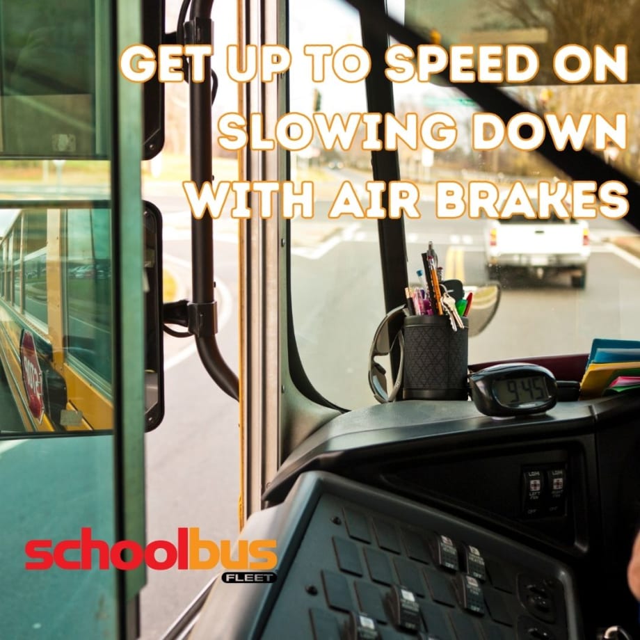
Air brakes have proven their worth over the decades, but new drivers may be unfamiliar with them.
Image: Canva
- Earning an air-brake endorsement may not ensure complete understanding of the air-brake system for school bus drivers.
- A primer on air brakes serves as a useful resource to bridge knowledge gaps for school bus drivers.
- Understanding air brakes is crucial for safe and efficient operation of school buses.
*Summarized by AI
Air brakes are a wonderful, time-proven invention. Wondering do school buses have air brakes? Although they’ve been now around for several decades, new school bus drivers have no experience with them. This article is aimed at helping drivers understand the function and operation of air brakes on a school bus.
There are three basic circuits in all modern air brake systems:
The charging system that supplies air for the brake system
The service system that is used for normal braking
The emergency/parking system which, as the name implies, is used in an emergency and for parking.
Understanding the Air Compressor
The heart of the air brake system is the compressor, which is often directly coupled to the engine. It also can be engine mounted or belt driven. In all cases, the compressor turns any time the engine turns.
Most compressors are fed oil directly from the engine’s pressurized oil system. The majority of compressors also use the engine’s cooling system.
To regulate the air system pressure, a governor is used. At 120 psi, typically, the governor will cycle, lifting the compressor unloading valve(s). Compressing ceases even though the compressor is still turning. When the system pressure falls to approximately 100 psi, the governor again cycles. This allows the unloading valve(s) to seat, and the compressor brings the system pressure up to the governor’s upper limit.
In the unlikely event of a governor upper limit failure, where the compressor continues to pump, a “pop off” or safety valve, typically set at 150 psi, will relieve system pressure.
How it Works: Storing the Air
Air reservoirs are mounted in various locations and are generally plumbed together with one-way check valves. The reservoirs store the air pressurized by the air compressor and stand ready when called upon to supply air to the brake chambers.
The first reservoir downstream of the compressor is called the wet tank because it catches water condensation and oil, byproducts of the compressor. This reservoir should be drained daily, assuring these byproducts are kept out of the air system components downstream.
Air dryers and automatic drain valves are found on many newer school buses; however, daily manual draining ensures no contaminates migrate into critical components, such as brake valves and chambers. The air distribution system utilizes many conduits, including rubber hose, nylon tubing, copper pipe or steel-braided hose.
Detailing the Air Brake Service System
The brake foot valve (left side of the throttle) technically comes in several versions. In all cases, however, it simply functions as a pressure regulator.
When the foot valve is at rest, no service air flows to the brake chambers, and the brakes at each wheel are released (assuming the parking/emergency system is not activated). As the valve is depressed, regulated air pressure is supplied to each service brake chamber.
The harder the foot valve is depressed, the higher the regulated pressure to the brake chambers. Conversely, as the foot valve pressure is reduced, the air pressure is simultaneously reduced to the brake chambers, and thus the brakes can be “feathered.”
The service brake chambers found at each wheel simply convert air pressure that comes from the foot valve to a mechanical force. Within each brake chamber is a diaphragm. One side of the diaphragm is exposed to the air pressure from the foot valve (service air), while the other side is exposed to atmospheric pressure.
As service air pressurizes the diaphragm, it pushes against a metal disc that has a metal rod attached to its center. The rod extends from the chamber and is connected to a lever. Mechanical force is generated as service air pressure against the diaphragm moves the disk and rod. This mechanical force via the lever arm rotates a shaft supported on bushings. The supported shaft’s outer end has a cam attached, called an “S” cam. The “S” cam supports one end of each brake shoe within the drum, while the other end of the shoe is mounted to a non-rigid anchor.
As the cam rotates via the mechanical force generated by the service brake chamber, the brake shoes are forced against the brake drum. Since the brake shoes are anchored at one end and the drums turn with the wheel, braking action occurs. This lever arm is called a slack adjuster and is the point where the brakes are adjusted.
Wedge brakes are a variation to the above. The brake chamber pushes directly on a wedge to move the brake shoes against the brake drum, thus eliminating the need for an “S” cam. Wedge brakes are rarely used on school buses.
Disc brakes are still another variation in that the air chamber mechanically operates a caliper that is used to clamp “pads” against a “disc” that rotates with the wheels. In summary, service air is applied to the brake chambers, converting air pressure to mechanical force. The mechanical force is then used to move the stationary brake shoes or pads against the brake drums or rotors. Since the drums or rotors are directly connected to the rotating wheels, braking occurs.
Air Brake Superiority
Several features make air brakes superior to hydraulic brakes. The first is that small leaks can be tolerated in an air brake system. The second is that the parking brake system also provides a fail-safe emergency system. (Some newer hydraulic brakes have a similar system).
In addition, air brakes are used for more severe applications, such as mountainous terrain, where hydraulic brakes can be overtaxed. The air chambers found on the rear axle only have two chambers and two diaphragms.
The chamber closest to the mounting studs is the service air chamber and receives air from the foot valve as explained previously. The second chamber is totally different in that an extremely powerful spring is located on the atmosphere side of the diaphragm, opposing the pressurized side of the diaphragm.
This means that with no emergency air pressure, the double chamber will stroke, and the rear brakes will be applied (no service air needs to be present). Air to oppose the springs comes from the parking (emergency) circuit, not from the foot valve service air.
What About the Parking/Emergency System?
The parking valve is typically located on the dash. With normal system pressure, pushing the valve “in” causes air to flow to the parking (emergency) side of the double air chamber, retracting the push rod against its applying spring and releasing the brakes. The parking/emergency system is spring applied and air released. The push/pull dash parking valve is unique in that once the supply pressure drops to the valve’s internal setting (generally between 20 and 45 psi), the valve will automatically pop out, thus fully applying the rear spring brakes.
In an emergency, the parking valve can be manually pulled out at any time, and rear braking will be experienced. In addition, the parking valve may be manually pulled out at any time in an emergency, and again, braking will be applied to the rear brakes.
Understanding that the parking/emergency brake system uses the bus’ rear brakes and that it takes air pressure to release them explains why a bus that has not been used for an extended period of time and has lost air pressure will have heavy brake drag until there is sufficient air pressure buildup to cause the rear brakes to fully release.
Always wait until the warning buzzer is off before moving. All buses built in 1975 and thereafter have a dual brake system. One system operates the front brakes, while the other system operates the rear brakes. These systems can be readily identified by the presence of a single gauge with two needles. (Two single-needle gauges are also used.) In dual systems, should air be lost in the front system, the rear braking system will stop the bus.
Conversely, should the rear brake air supply be lost, through special valving, the rear spring brakes’ release air will be bled off in direct proportion to the front brake application air pressure, thus stopping the bus normally. In either of the above cases, the low-air warning systems will be activated due to low air pressure in the failed system; however, the bus can be safely pulled to the side of the road and stopped.
Do’s and Don’ts of Air Brakes in School Buses
With spring-type parking brakes, air brakes are considered fail-safe. This is true with the following stipulations: brake components cannot be damaged; brakes must be in proper adjustment; and the large spring found within the double brake chambers must not be broken. Brake adjustment on drum brakes is critical.
As previously stated, the brake chamber strokes, and via linkage, mechanically moves the brake shoes against the brake drum. Typically, the maximum stroke is 1.75 to 2.5 inches, depending on the size and type (standard vs. longstroke; front vs. rear) of the brake chamber. As the brake lining wears, the shoe/drum clearance continues to increase.
Excessive clearance (brakes out of adjustment) will cause the brake chamber(s) to stroke near their maximum before the shoes contact the drum. With the brake chamber(s) near maximum stroke, as the brake drum heats and expands, the shoes follow the expansion.
Due to the mechanical advantage (ratio) between the brake chamber rod and shoe movement, very little drum growth will cause the chamber rod to move sufficiently to become fully stroked. Braking action on that wheel will be greatly reduced. Note: Heated rotors on disc brakes have little or no effect on chamber stroke.
Once the above concept is understood, it is easy to grasp that descending a grade with the brakes out of adjustment can spell impending disaster.
Air Brake Adjustment is Necessary
The maintenance department is required to check the brake adjustment every 3,000 miles. After a brake reline, brake adjustment must be checked every 500 miles until the shoes seat to the drums. Brake chamber stroke on automatic slack adjusters should also be verified every 3,000 miles.
If you ever notice the brakes smelling hot after descending a grade, or if at anytime they seem sluggish, turn in a trouble report to have the brake adjustment checked. All standard pre-trip forms include several routine but critical air brake system tasks and checks:
Drain wet tank
Warning systems “on and off” pressures (55 psi minimum; 75 psi maximum)
Compressor build up time (85 to 100 psi within 45 seconds with the engine operating at the vehicle manufacturer’s maximum recommended rpm).
Air loss (at full air pressure, 2 psi maximum loss in one minute with service brakes released and 3 psi loss per minute with service brakes fully applied). Each morning as part of your pre-trip, drive the bus at 5 to 10 mph and apply the parking brakes. The bus should come to a quick, solid stop. This verifies that the spring brakes are functioning. Being diligent about pre-trips not only protects you and your passengers from harm, but may also reduce your from liability exposure. In the event of an equipment problem that leads to an accident, your pre-trip documentation may very well become your best friend.
About the Author: Richard Stafford is an ASE Master School Bus Technician.
Quick Answers
An air-brake endorsement indicates that basic competency has been met, but it doesn't cover the detailed functioning and troubleshooting of the air-brake system.
*Summarized by AI
More Maintenance

Cummins on Smarter, Simpler Engine Innovation
Cummins discusses its first-ever gasoline engine for school buses, EPA 2027, and why bus fleets still want durable, simpler internal combustion options.
Read More →
Report: 72% of Diesel School Buses Now Use Advanced Low-Emission Engines
New data shows advanced low-emission diesel technology continues expanding across school bus fleets, even as electric bus adoption gains momentum.
Read More →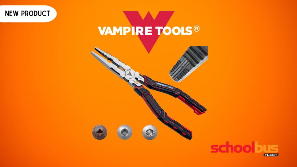
Vampire Tools' CAIMAN 7.5-Inch Multi-Purpose Screw Extractor Long-Nose Pliers with Crimper
Vampire Tools introduced the VAMPLIERS Caiman 7.5-inch multi-purpose pliers, combining screw extraction, cutting, crimping, and gripping functions into a single tool designed for fleet maintenance professionals.
Read More →
How Advanced Diagnostics Helps Bus Fleets Stay Ahead of Repairs
Chat with Noregon’s Kevin Smallhorn at ACT Expo about bus diagnostic tools, telematics integration, CNG maintenance support, and strategies to help reduce downtime and improve uptime.
Read More →
How School Bus Fleets are Getting Ahead of Breakdowns
Don’t let bus downtime wear you down. Here’s how bus operators are shifting from manual processes to AI-powered, data-driven maintenance systems for improved reliability and safety.
Read More →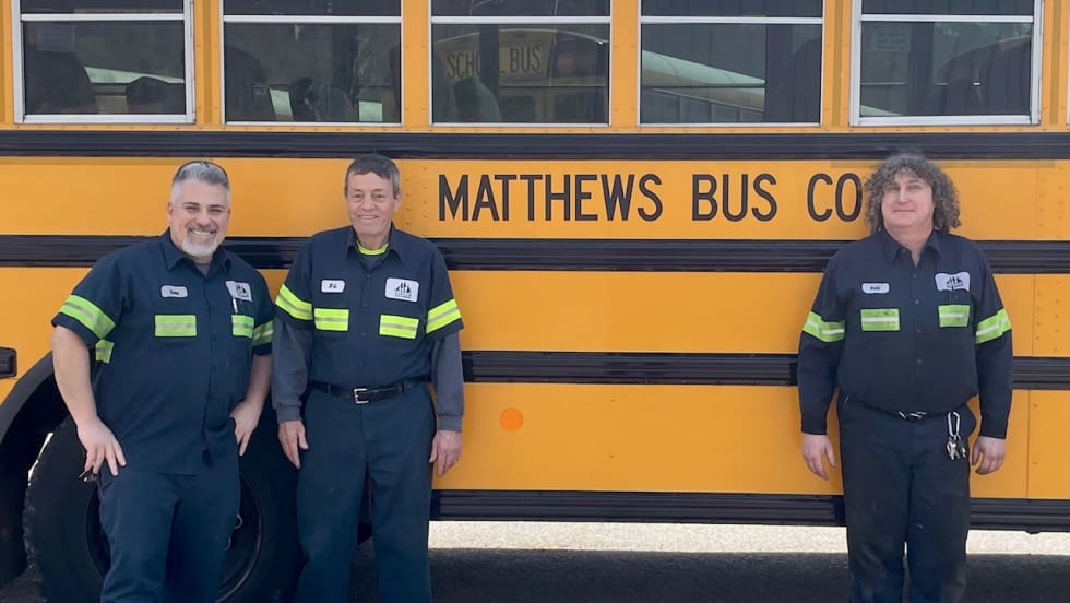
Pennsylvania School Bus Maintenance Team Praised for Dedication to Safety
Matthews Bus Company’s West Jefferson received a letter of commendation from the Pennsylvania State Police for their fleet inspections.
Read More →
2026 State of Student Transportation Report
Student transportation teams are being asked to do more with less, facing driver shortages, rising costs, and increasing safety expectations. This report uncovers how fleets are adapting, where technology is making the biggest impact, and why student ridership tracking is emerging as a top priority. Download the report to explore the key trends shaping 2026 and what they mean for your operation.
Read More →
From Chaos to Clarity: How School Districts Are Running Leaner Transportation Operations
Covering 38 routes on a Friday afternoon. Buses idling while routes overlap. Parents calling nonstop about late arrivals. Sound familiar? This whitepaper explores how district transportation leaders solved these exact problems — and what measurable results followed.
Read More →
The New Playbook for Safer, Smarter School Bus Maintenance
As school districts juggle aging buses, technician shortages and rising safety expectations, proactive fleet maintenance is becoming essential. This guide explores how telematics, predictive maintenance and real-time vehicle data can help transportation departments reduce breakdowns, extend vehicle life, improve compliance and keep students safer on the road.
Read More →
2026 School Bus Fleet Vendor Directory & Buyer's Guide
Searching for the right equipment, technology, or services for your school transportation program? This industry guide brings together manufacturers and suppliers across the entire school bus market, all in one place. Download it to find the partners who can help move your operation forward.
Read More →